MAE 4190 Fast Robots
10 minutes read •
This page showcases my work in MAE 4190 Fast Robots, a course centered on the systems-level design and implementation of dynamic autonomous robots. Over the semester, I designed and fabricated a fast autonomous car with dynamic system modeling and reactive control via integrating gyroscope and time-of-flight sensor feedback on an embedded processor. The course also explored the advantages of partial off-board computation, low-latency software, and noise-tolerant implementation.
Highlights from Each Lab
Below are highlights from each lab building up to the final lab where I achieved fully autonomous navigation and path planning via real time localization and linear/angular PID control. For detailed documentation of each lab with code reference my Fast Robots site.
Lab 1: Artemis Setup and Communcation
Key Takeaways:
- Installed and configured the Artemis successfully
- Set up a reliable communication link between Artemis (peripheral) and computer (client)
- Built methods for both real-time and batch data collection to compare responsiveness and accuracy in sampling
- Customized UUIDs to avoid device conflicts and wrote Python scripts for BLE command transmission and processing
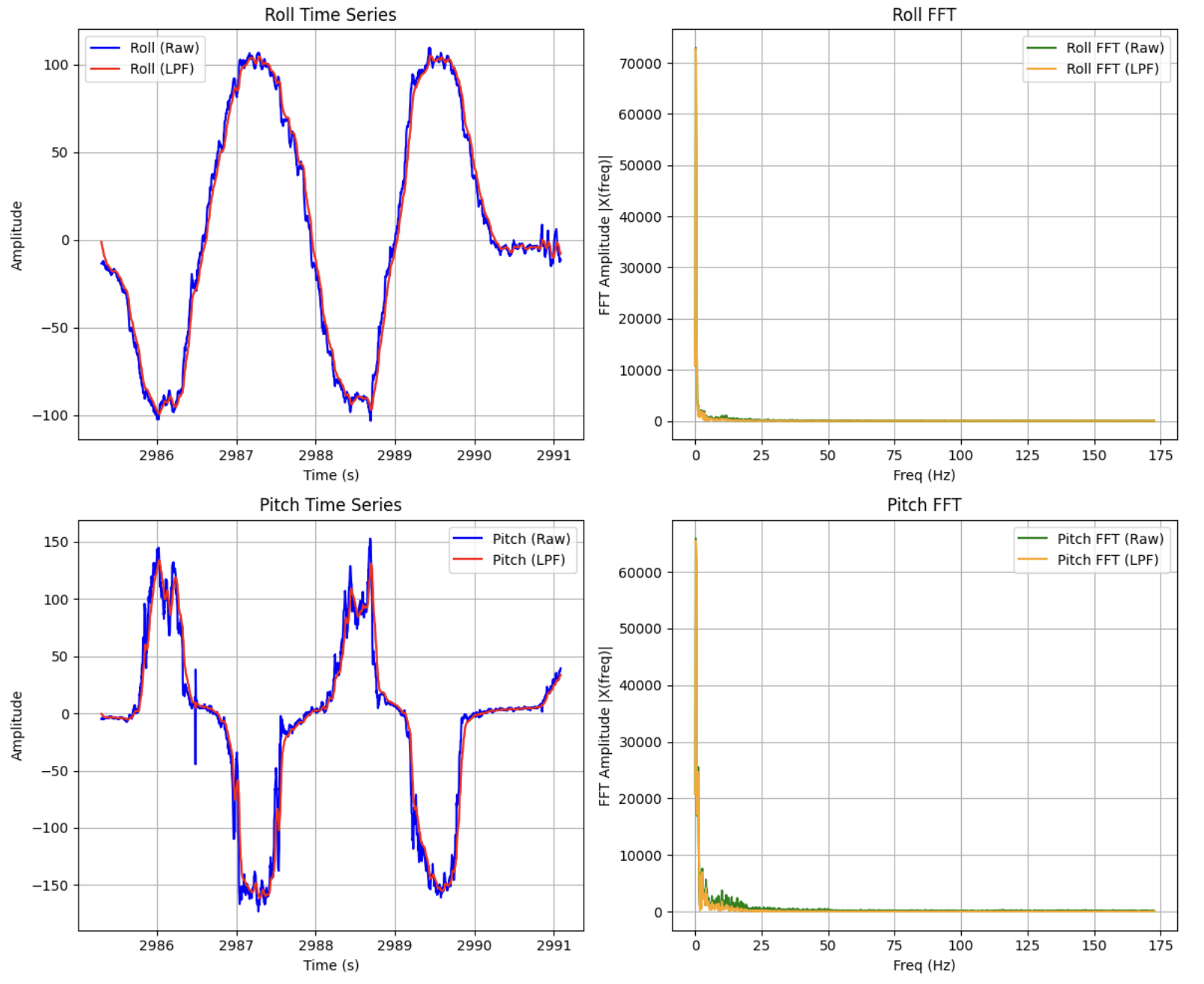
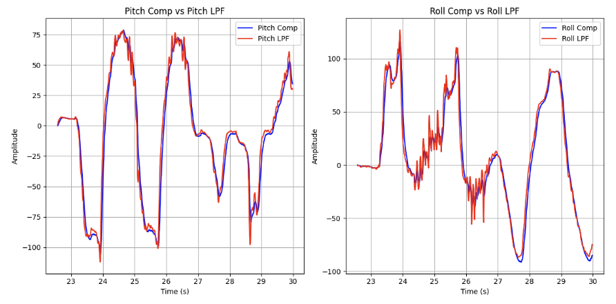
Lab 2: IMU
Key Takeaways:
- Configured ICM-20948 IMU over I2C, verified accelerometer and gyroscope readings.
- Converted accelerometer outputs to pitch and roll; validated accuracy across ±90°.
- Implemented FFT + low-pass filter (cutoff 5 Hz) to characterize and reduce noise while preserving motion signals.
- Integrated gyro drift-prone data with accelerometer stability using a complementary filter (α = 0.0876).
- Achieved ~350 Hz sample rate, 25 seconds of buffered IMU data, and confirmed smooth motion capture during stunts.
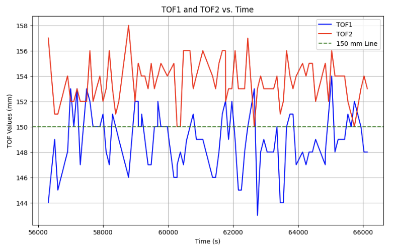
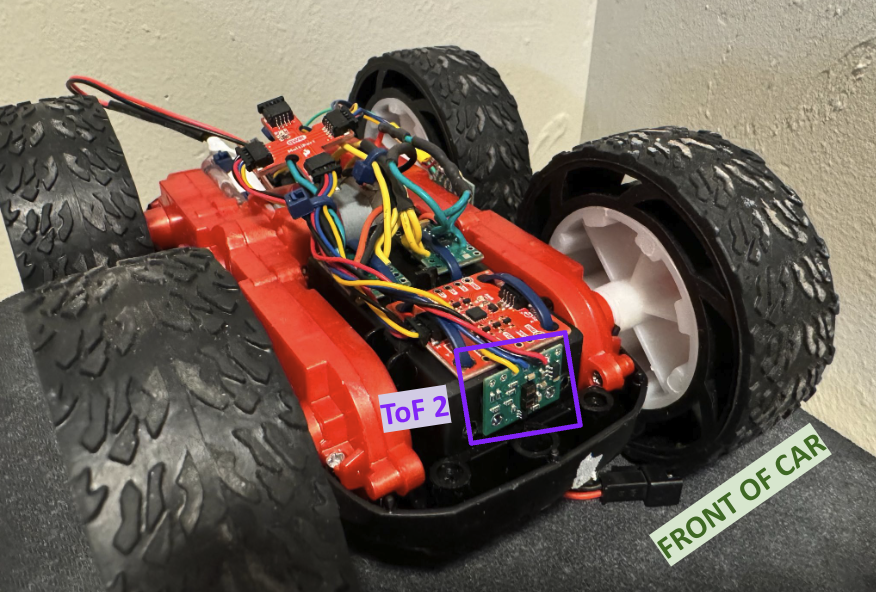
Lab 3: Time of Flight Sensors
Key Takeaways:
- Used XSHUT pin to reassign I2C addresses, enabling two ToF sensors in parallel.
- Wired sensors to Qwiic breakout with soldered battery leads, tested mounting layout.
- Verified accuracy across 100–200 mm; identified noise below 40 mm due to sensor limits.
- Measured ~11 Hz sampling rate; confirmed ToF was the bottleneck compared to ~98 Hz IMU.
- Collected synchronized ToF + IMU data over BLE, validating angle/distance correlation.
- Characterized ToF noise
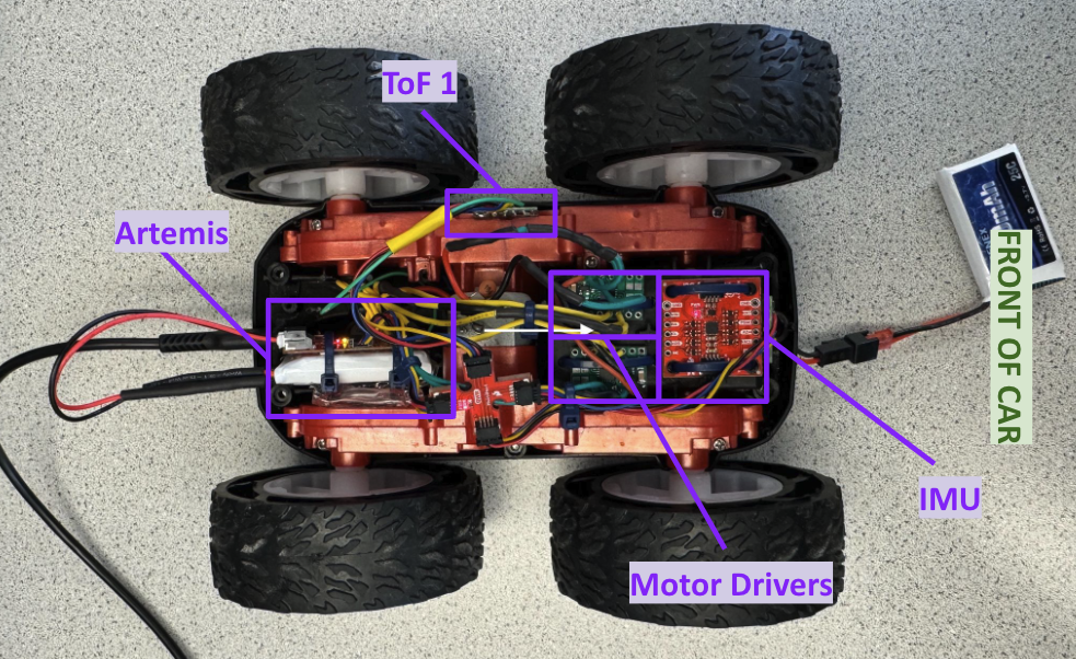
Lab 4: Motor Drivers and Open Loop Control
Key Takeaways:
- Designed drivetrain wiring: Artemis pins (13, A14, A15, A16) to dual motor drivers with PWM control.
- Used separate batteries for Artemis vs. motors to reduce noise and protect sensitive electronics.
- Verified PWM duty cycles on oscilloscope and tested forward/reverse/spin maneuvers.
- Determined lower PWM thresholds (35 forward/reverse, 110 spin).
- Calibrated wheel imbalance with multiplicative correction factors (1.05, 1.3) to achieve straight-line motion.
- Fully integrated IMU, ToF, motor drivers, and power onto the chassis for open-loop tests.
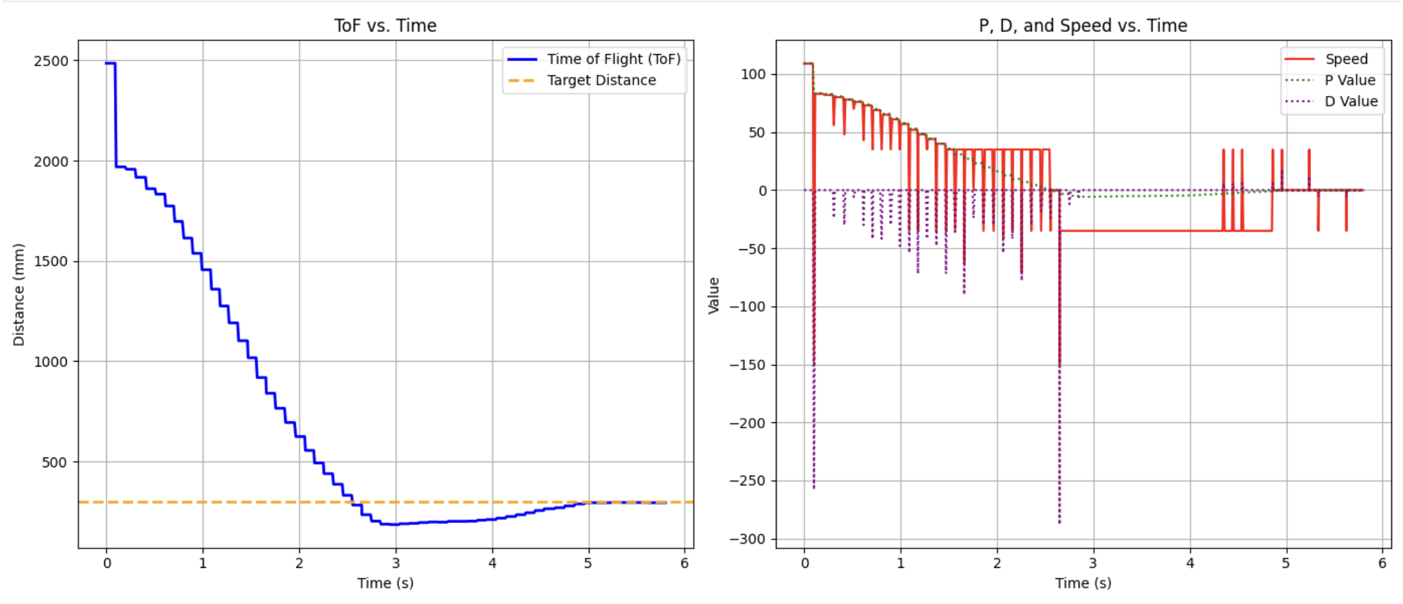
Lab 5: Linear PID Control and Linear Interpolation
Key Takeaways:
- Implemented BLE command PID_CONTROL to send PID gains (Kp, Ki, Kd) and target ToF distance to the Artemis.
- Developed pid_speed_ToF() function with logic for tolerance, saturation, motor deadband, and direction switching.
- Tuned Proportional control (Kp = 0.05–0.08) to keep PWM speeds reasonable at large errors; deadband added for small errors.
- Added Derivative control (Kd ≈ 6) to slow the robot proportionally to error slope, preventing overshoot into the wall.
- Found ToF sampling limited to ~9.24 Hz, causing discrete jumps in derivative term.
- Implemented extrapolation to achieve ~172 Hz loop speed, interpolating distances between ToF readings.
- Verified with PD + extrapolation (Kp = 0.2, Kd = 3): robot could start 2.7 m from wall and still stop at 1 ft target without overshoot.
- Demonstrated near-zero steady-state error at higher speeds, eliminating need for integral term.
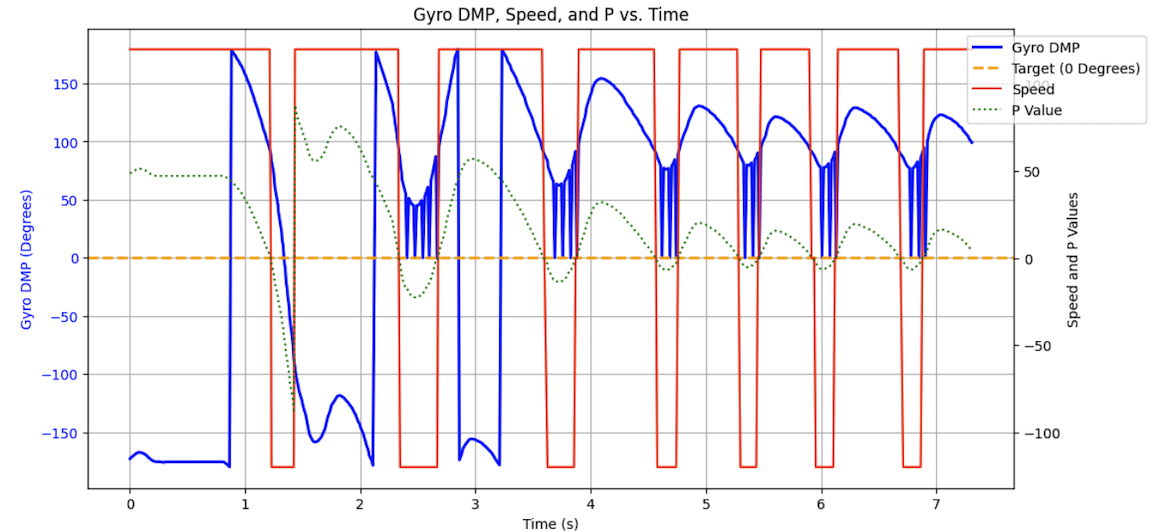
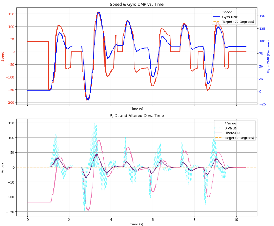
Lab 6: Orientation Control
Key Takeaways:
- Implemented PID turning control loop using IMU DMP yaw data.
- Mapped PWM outputs into robot’s floor/ceiling bounds to achieve smooth PID instead of binary switching.
- Added low-pass filter (𝛼 = 0.1) on derivative term to reduce noise and derivative kick.
- Fixed overshoot by inserting 1-second low-PWM delay before rotation.
- Tuned gains to Kp=1.65, Kd=130, achieving ±2° accuracy in disturbance tests and waypoint navigation.
- Verified IMU DMP sampling at ~549 Hz, sufficient for high-speed control loops.
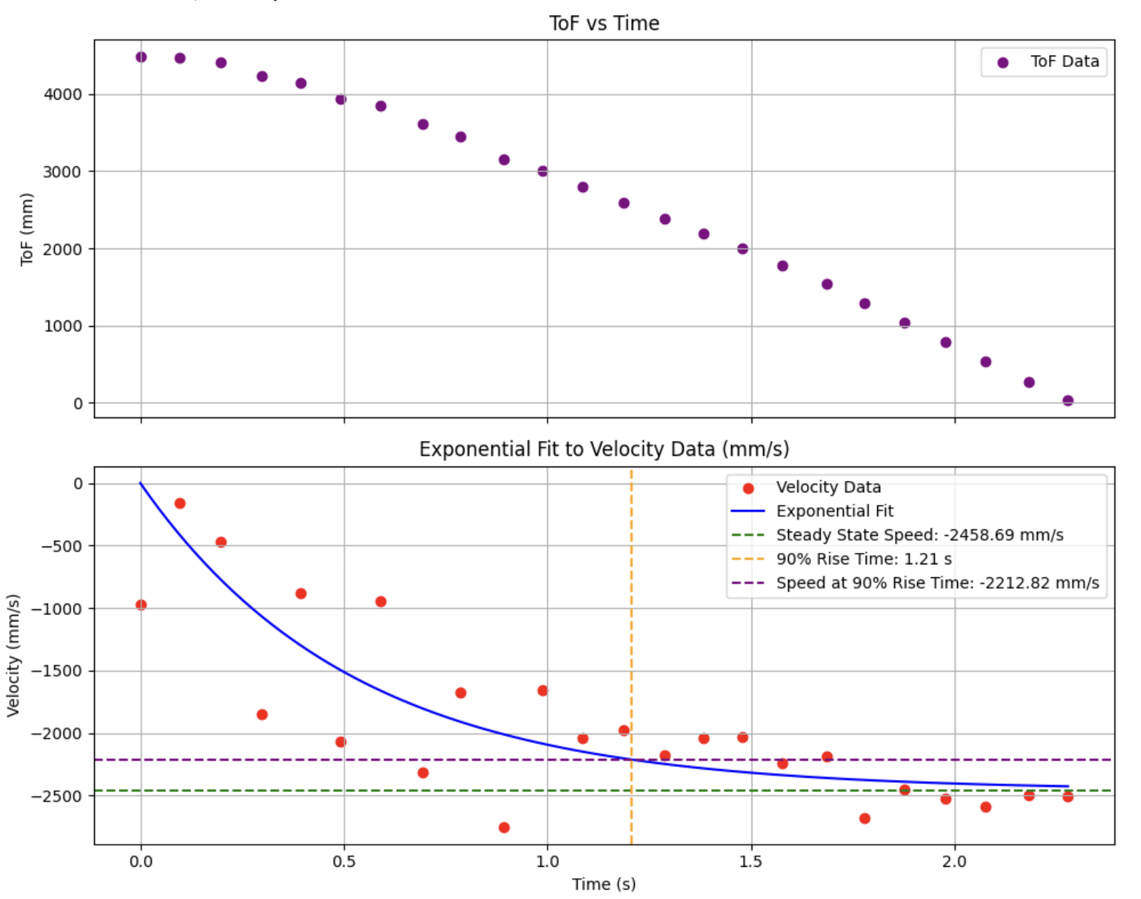
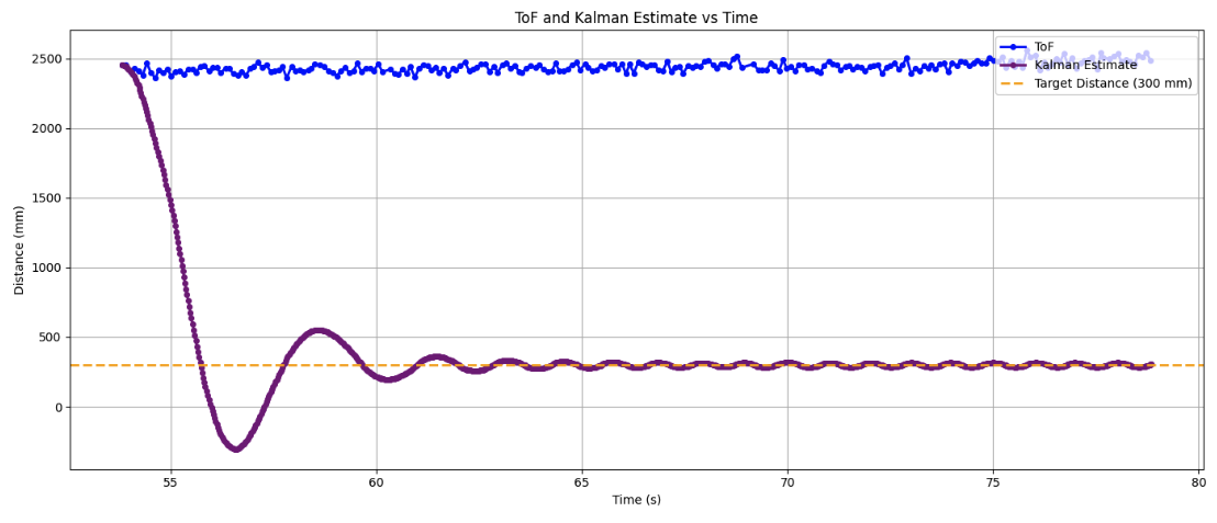
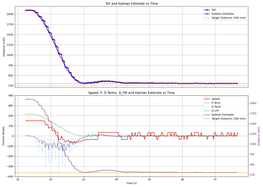
Lab 7: Kalman Filter
Key Takeaways:
- Modeled car dynamics with drag and mass parameters estimated from ToF velocity profiles
- m ≈ 0.39 kg, d ≈ 0.41 kg/s
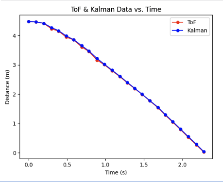
- Built Python Kalman simulation to fuse ToF data with state-space dynamics
- Tested trust weighting by varying sigma1, sigma2, sigma3
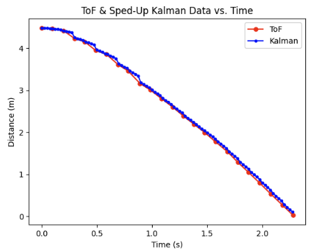
- Confirmed filter could run at ToF sampling rate (95 ms) and faster PID loop rate (20 ms)
- Integrated filter on-board: predicted state when ToF was unavailable, improving control continuity
- Demonstrated proportional control overshot wall stops, but PD + Kalman achieved smooth approach and near-zero overshoot at 300 mm target
- Discussed parameter tuning:
- m, d set dynamics
- u scaling improved model fit
- sigma values balanced model vs. sensor trust
Lab 8: Stunts
Key Takeaways:
- Designed flip stunt triggered via Bluetooth (CMD.STUNT), parameterized by wall distance for flexible tuning
- Used ToF + Kalman fusion to track distance in real time during stunt execution
- Tuned state-space A/B matrices to improve distance predictions; still noted velocity underestimation in KF
- Achieved consistent flips on mat placed 300 mm from wall; best trials completed in about 2.3 s
- Corrected drift with motor scaling factors (0.95 forward, 0.90 reverse) to keep trajectory straight
- Explored added front mass for nose-dive, but found battery charge level had greater effect on success
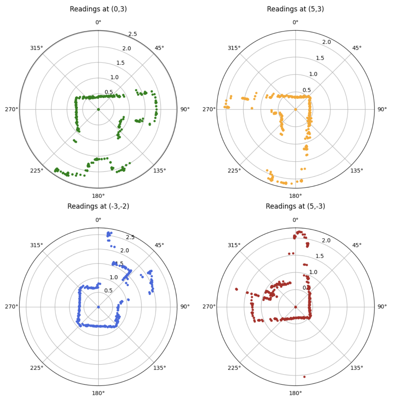
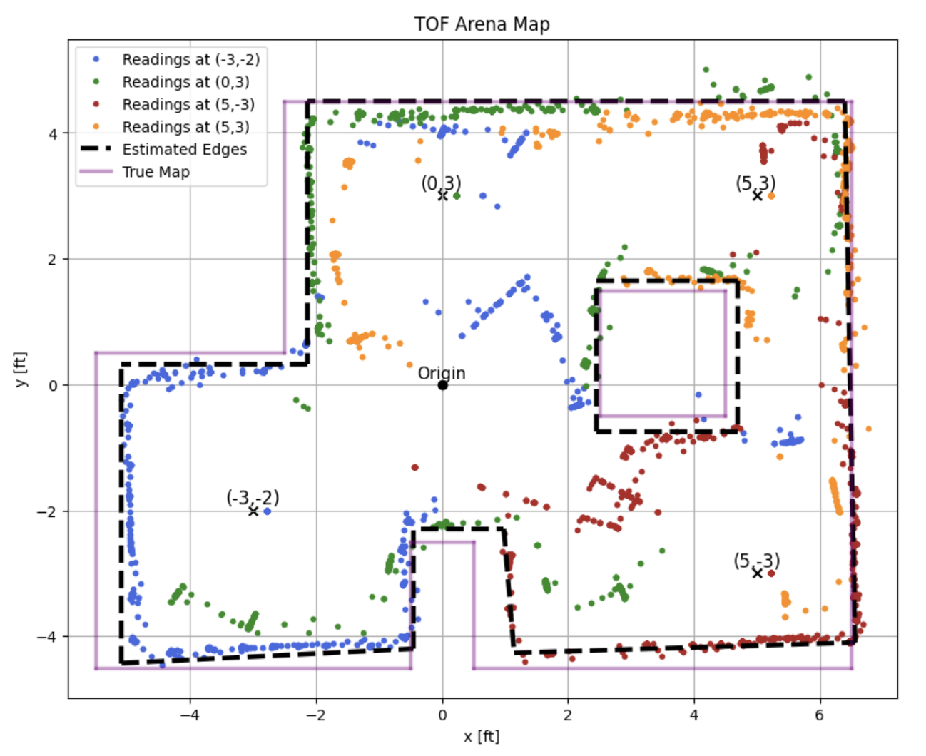
Lab 9: Mapping
Key Takeaways:
- Implemented on-axis spin using IMU DMP yaw control with PID, turning in 12° steps for 30 total increments
- Collected about 2780 ToF samples per rotation; achieved ~1.5 in average positional error due to wheel drift/slip
- Verified minimal overshoot at slow spin speeds; tradeoff between accuracy and memory usage
- Converted raw ToF readings into global coordinates using homogeneous transformation matrices
- Built full-room ToF map; noise caused arcs and spurious lines, but overall map aligned closely with ground truth
- Estimated walls from ToF scans and overlaid them with the known map for validation
Lab 10: Grid Localization using Bayes Filter
Key Takeaways:
- Implemented Bayes Filter in Python to probabilistically track robot state (x, y, θ) in a discretized 3D grid
- Built odometry motion model: initial rotation, translation, final rotation; incorporated Gaussian noise
- Developed prediction step to propagate belief via motion model; optimized by skipping negligible states
- Created sensor model using ToF likelihoods; updated belief grid via Bayesian inference
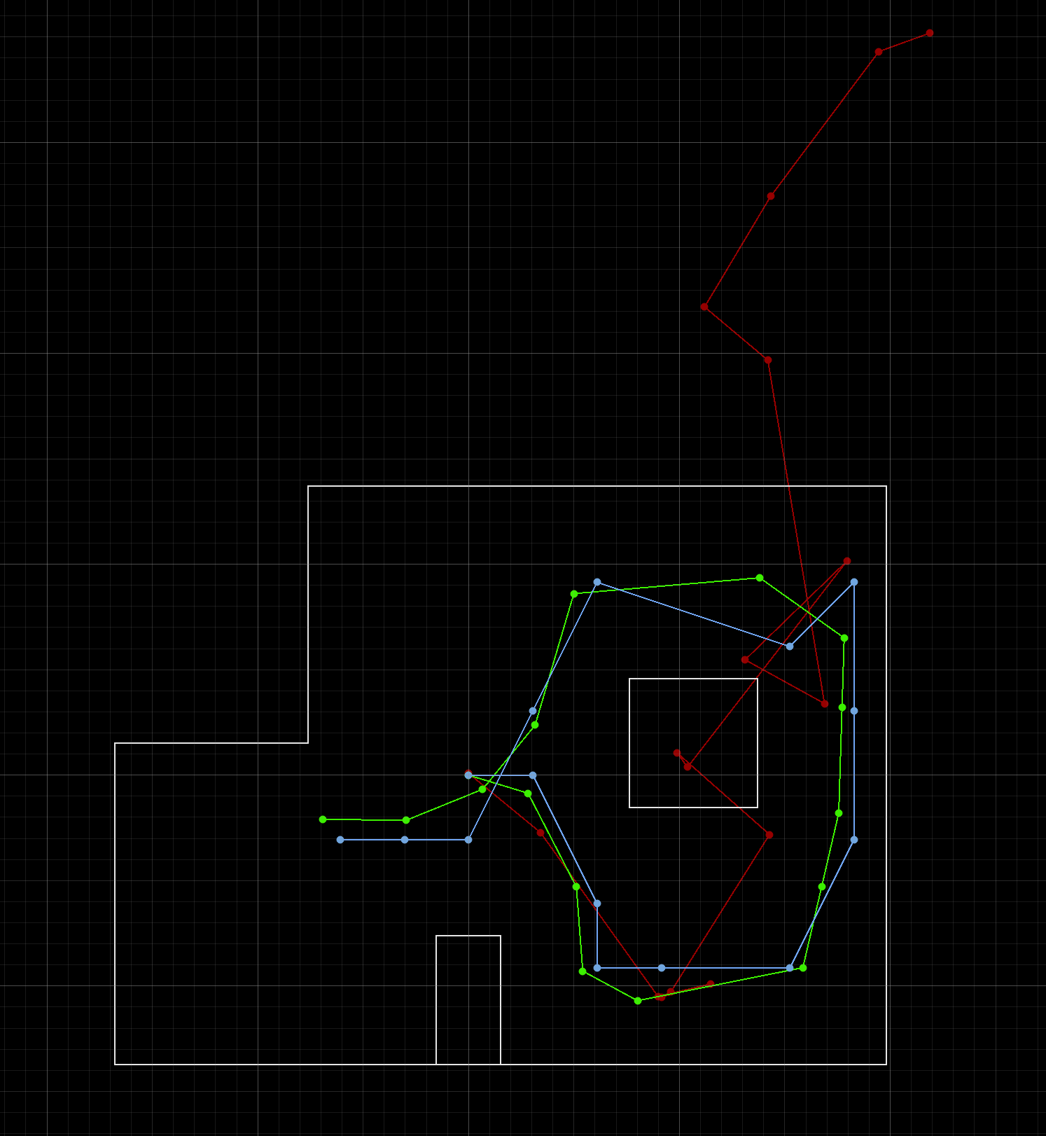
- Simulation showed odometry drifted, but Bayes Filter belief (blue) aligned closely with ground truth (green)
- Performed best near walls since shorter ToF distances produced more accurate sensor updates
Lab 11: Localization on the Real Robot
Key Takeaways:
- Implemented update step on robot: performed spins, collected 36 ToF readings at 10° intervals, and sent data over BLE
- Ensured accuracy by pausing 500 ms at each angle before capturing ToF
- Results: localized robot within ~8 in of true pose; ToF underestimation shifted beliefs closer to walls
- Adjusted ToF mounting angle and reduced sensor noise parameter (sigma = 0.05) for improved reliability
- Demonstrated successful belief updates at multiple coordinates; belief (blue) tracked near ground truth (green)
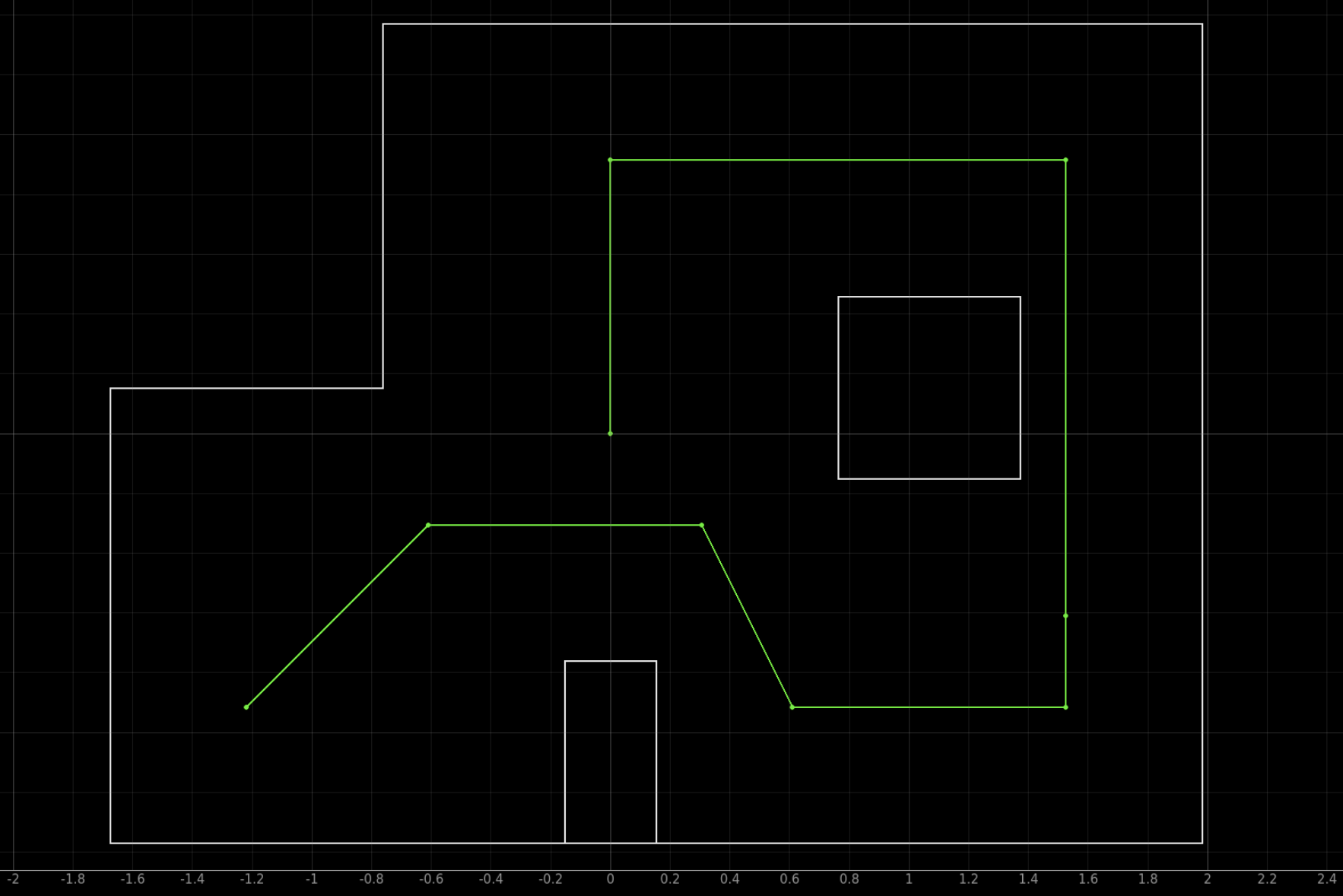
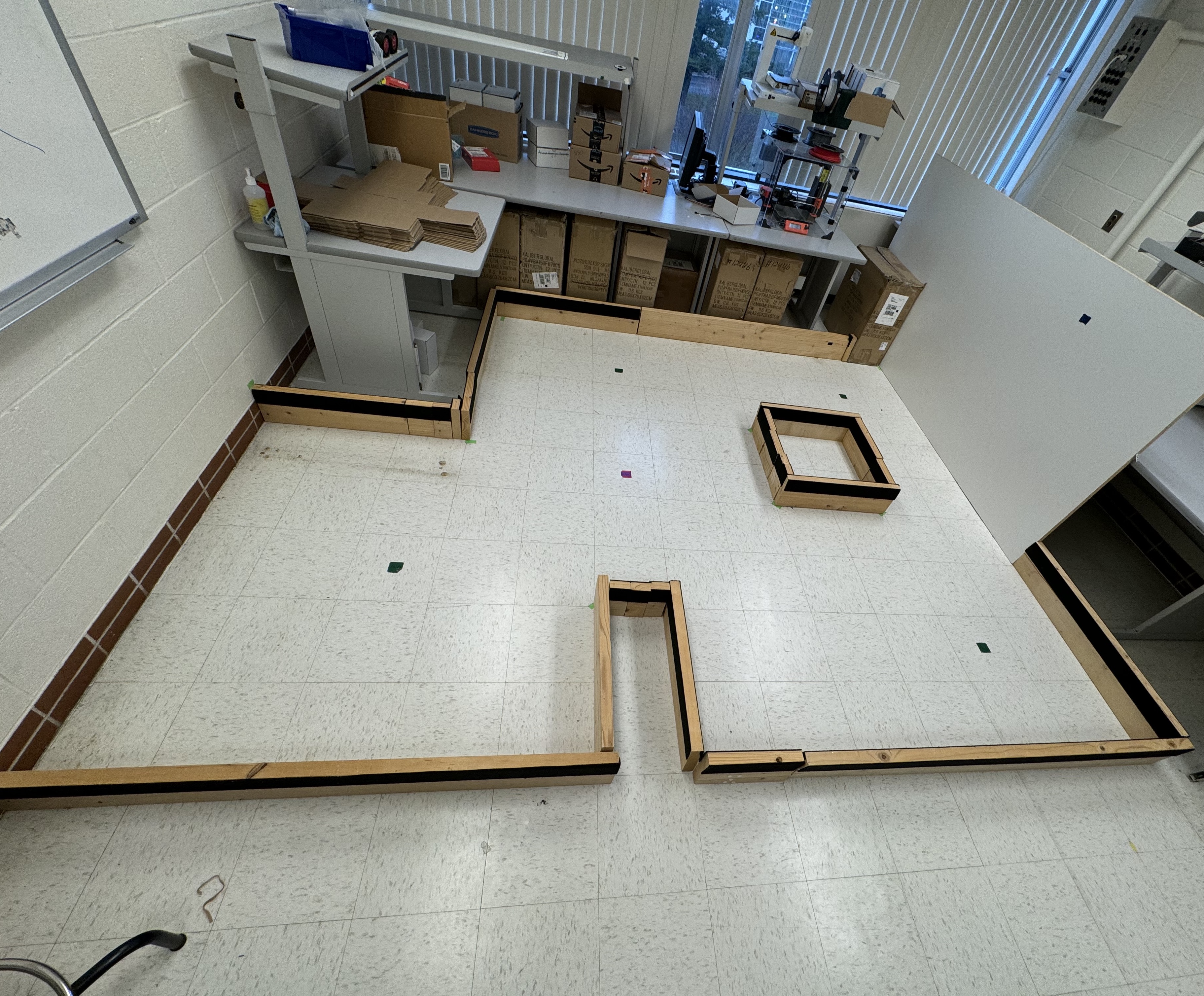
Lab 12: Path Planning and Final Project
Key Takeaways:
- Combined all subsystems: waypoint navigation, PID orientation/linear control, Kalman ToF filtering, and Bayes localization
- Defined waypoint list with localization flags for selective belief updates along path
- Orientation PID: computed heading with atan2, rotated using DMP-based control with cutoff timer
- Linear PID: calculated target distance via ToF and belief position; advanced to waypoint
- Ran localization scans at chosen waypoints using SPIN case (Lab 11 method)
- Early runs showed overshoot and derivative blow-up; final run achieved smooth autonomous navigation through all waypoints
- Demonstrated complete system integration: perception, control, and planning working reliably in the real arena