Lab 4: Motor Drivers and Open Loop Control
6 minutes read •
Prelab
System Wiring
I decided to use pins 13, A14, A15, A16 for control on the Artemis. This pin proximity does increase risk of shorting connections, however it allows for a more compact design and greater area of the board to be used for mounting to the car rather than having to avoid largely seperated pins. Furthermore, according to the data sheet pins marked with a (~) indicate PWM capability which is required to send signals to the motor drivers.
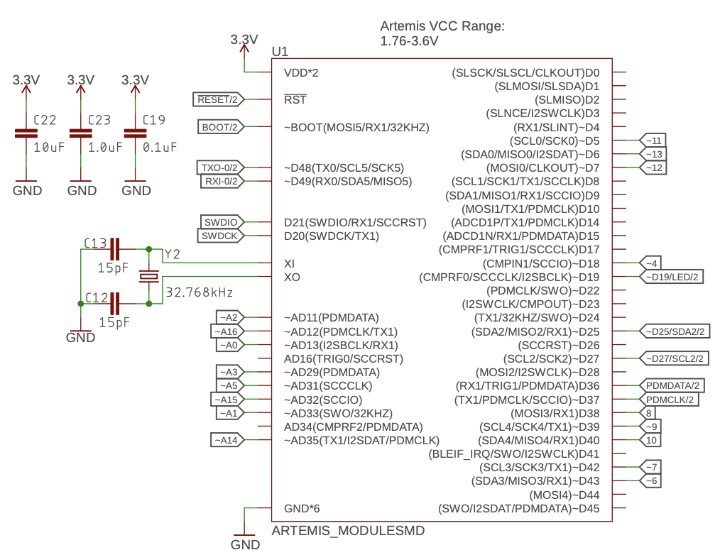
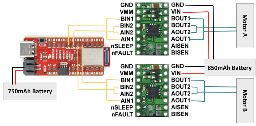
The motor driver electrical schematic used on my car is shown below:
Battery Discussion
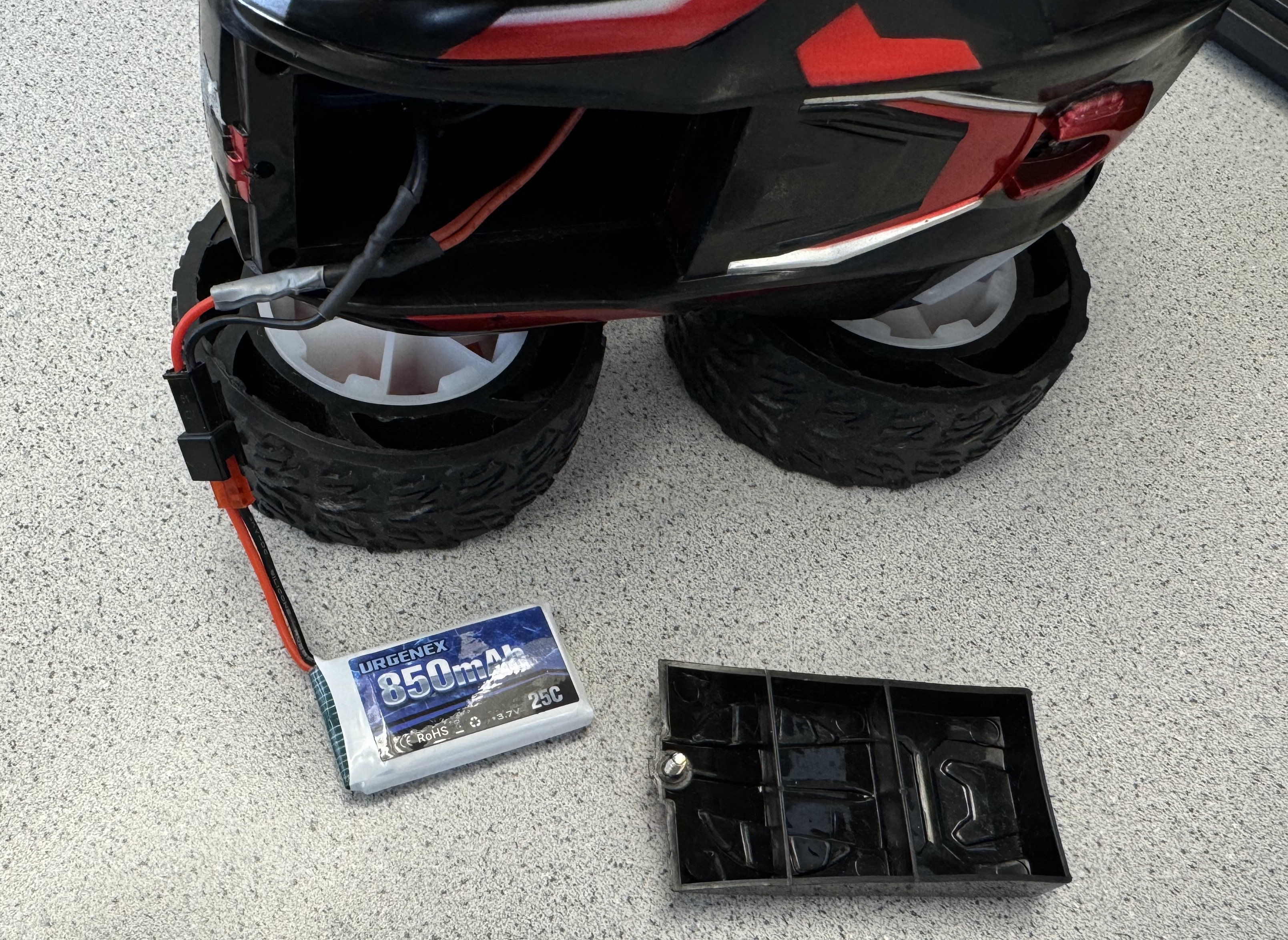
The Artemis and the motor drivers/motors are powered by separate batteries to help ensure operational stability, protect components, reduce noise, and increase battery lifetime. The two car motors can act as a disruptive inductive load, potentially creating large amounts of noise and posing a damage risk to sensitive parts. Thus powering the Artemis by a second battery allows the motors to run for longer and protect the Artemis circuit (all connected by signal wires) from the motor interferance and inductive load.
Lab Tasks
Power Supply and Oscilloscope Hookup
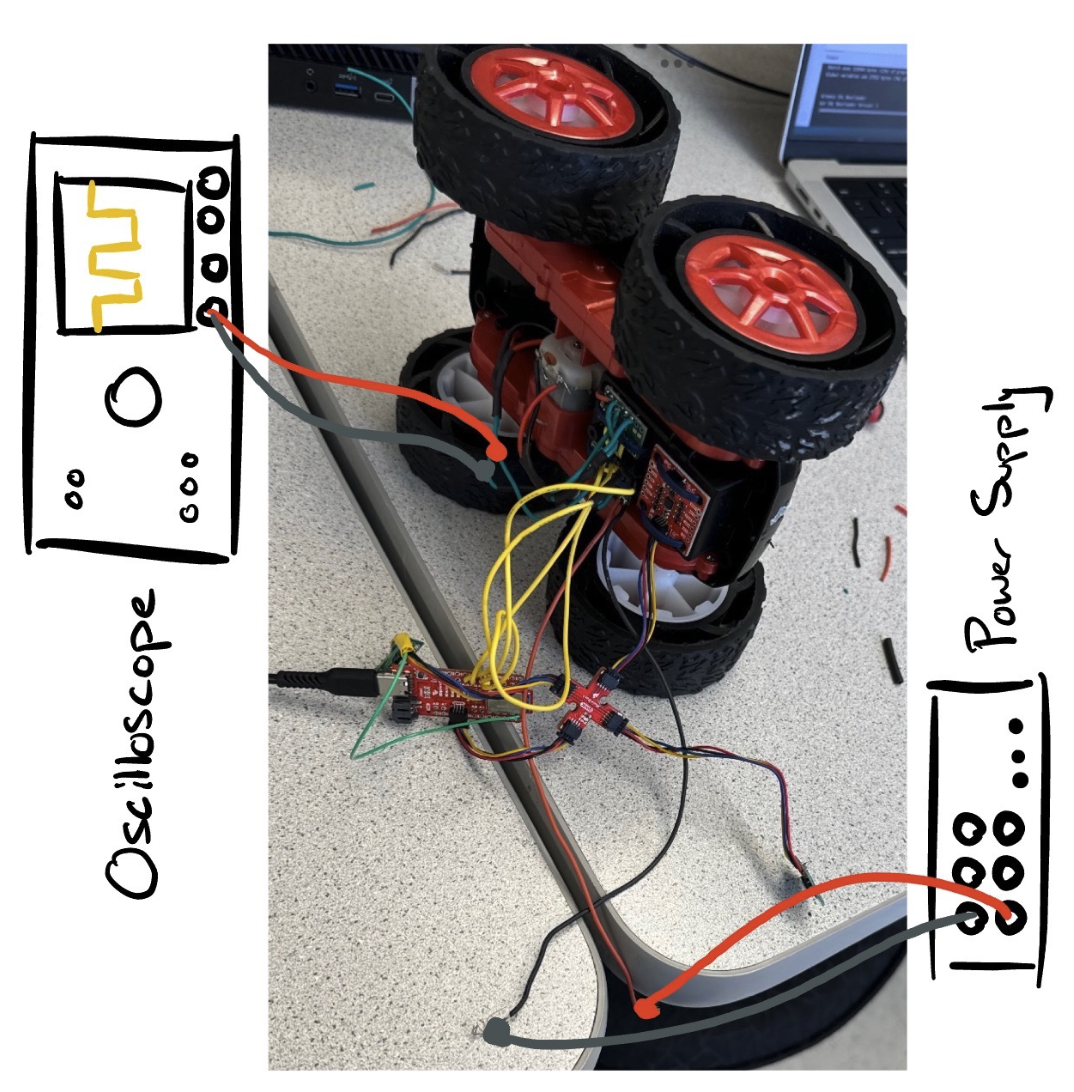
One motor driver was tested at a time by connecting the inner two OUT pins to the positive scope probe and the outer two OUT pins to the ground scope probe. I also connected VIN and GND to the power supply to power the driver. The power supply is set to 3.7V to simulate the 3.7V that would be supplied by the 850mAh motor battery. Below is a picture of the setup (the power supply and oscilloscope probing wires are drawn in to show the setup used to obtain the PWM signal before I soldered the parts to the car):
The following code was used to visualize the motor driver output:
void
void
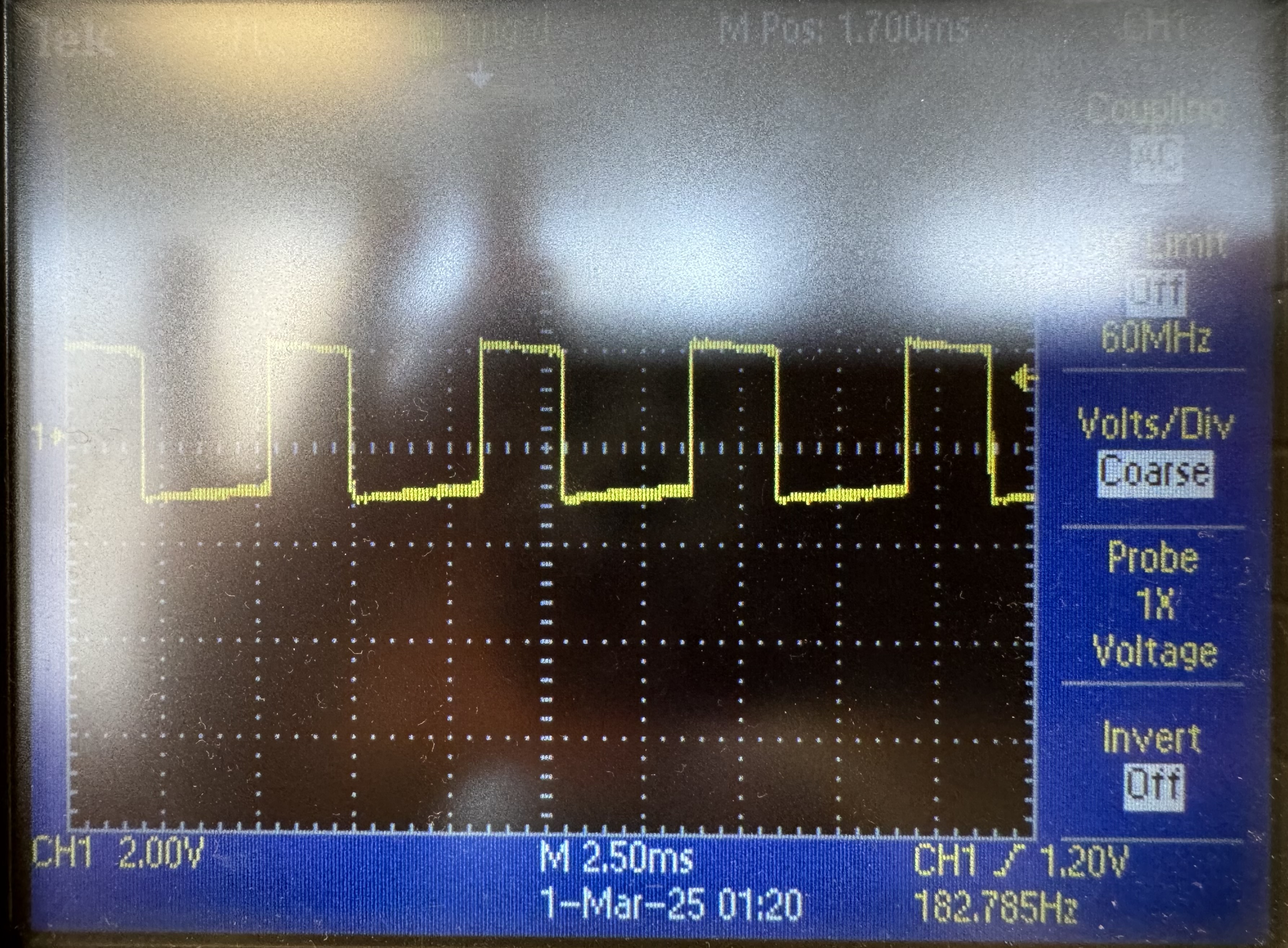
The analogWrite(AB1IN_LEFT,100) line indicated a 40% (100/255) duty cycle to pin 16. This was captured on the oscilloscope:
Motor Testing
The above code used to see the PWM signals on the scope were also used to run one side of wheels:
After confirming that both motor drivers successfully powered the motors, I tried running the car all together using the 850 mAh battery using the following code:
void
void
void
void
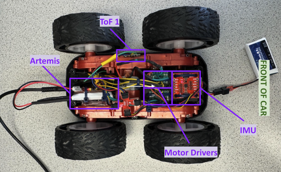
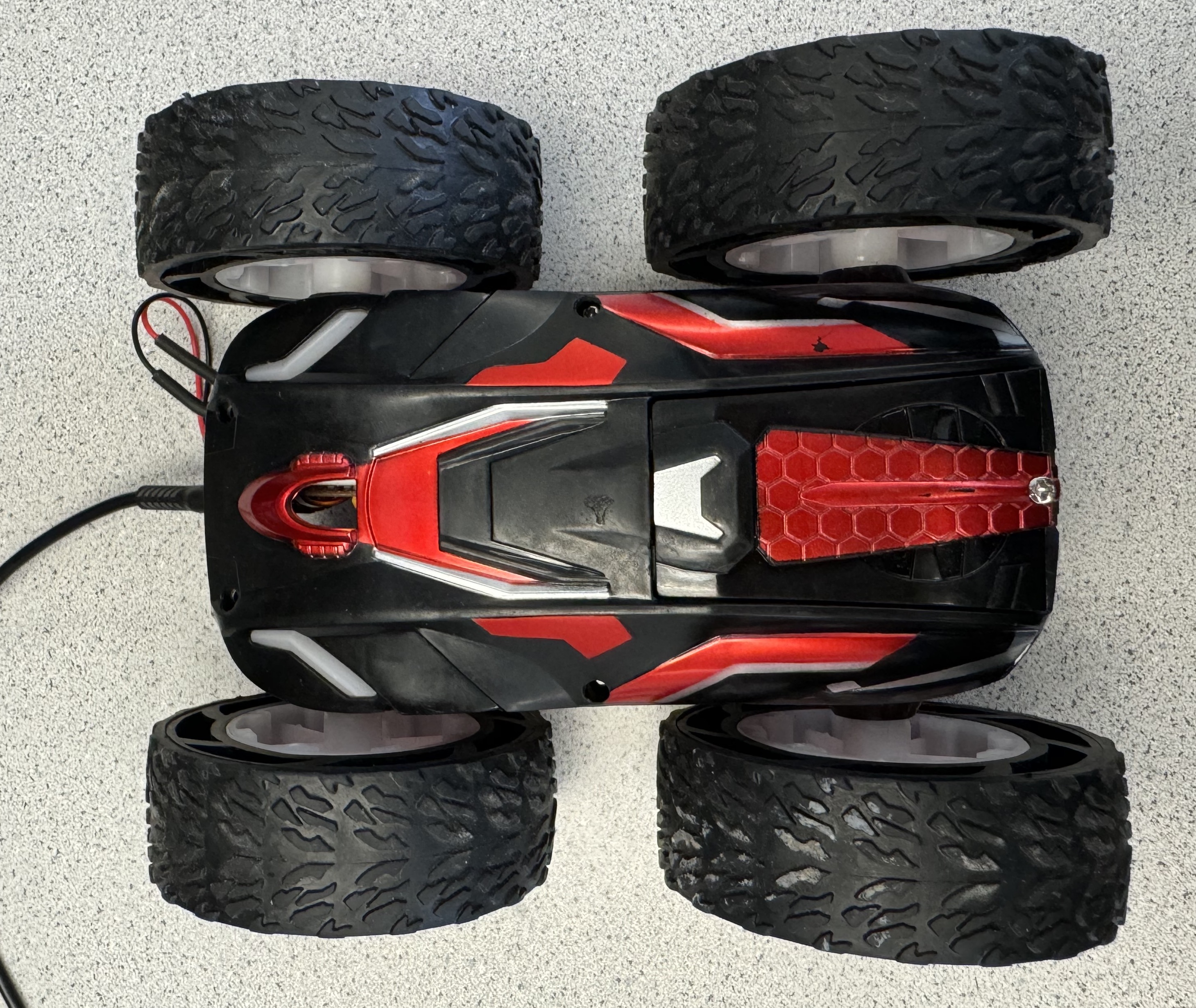
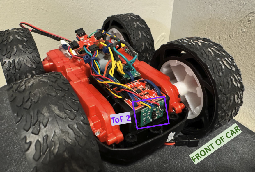
Complete Hardware Integration on Car
Below are images of the car after mounting all components. Holes were drilled and zip ties were used to strap down the IMU and both motor drivers at the front. Zip ties were also used to bundle the Artemis and 750mAh battery as well as for wire managment. Double sided tape was used to mount the two ToF sensors (one on the side and one at the front) and the Artemis/battery module at the rear.
Lower PWM Limit
I found that the minimum PWM value for which the robot needs to move forward, backward, and on axis by starting with a arbitrary small value and increasing it by 5 until the car no longer stalled. I found that on a fully charged battery the forward and backward lower limit PWM value is 35 and 110 for spinning on axis.
Here is a video of testing using those PWM values to go forward, in reverse, then spin on axis in both directions:
Open Loop Testing and Calibration
When first testing the car’s straightline preformance, it would instantly begin to veer to the right. I also noticed that when traveling in reverse the car had the same issue where the right side lacked power. To account for this I added a calibration factor to increase the PWM signal for the right set of wheels. Initially I went about this by simply adding a calibration factor to the PWM rather than scaling it via a multiplicative calibration factor. While I was able to get the car fairly straight doing this, it only really worked for a set speed. Given this, I decided to switch to a scaling calibration factor which you can see implemented in the code below. I started both scaling factors at 1 and increased them by .05 until I recieved steady straightline results (visible in the Open Loop Test video).
void
void
void
void
speedLineis the stright line speed for forward and reversespeedTurnis the turning speedcorrection_fis the calibration factor for forward wheel rotation (currently 1.05)correction_bis the calibration factor for reverse wheel rotation (currently 1.3)
To test a range of car capabilities, I had the car move straight, then in reverse, then rotate on axis in both directions before moving straight left at the end (note each tile is 13“x13“). The sequence of actions is set in the main loop() which gets called when the START_DATA_COLLECTION command flag is run over bluetooth.
Collaboration
I collaborated extensively on this project with Jack Long and Trevor Dales. I referenced Wenyi’s site for my wiring setup, initial motor testing code, and general outline for creating funtions to drive forward, spin right, etc. Special thanks to all TA’s that helped debug my electronics and car for hours before we realized I probably needed a new one!